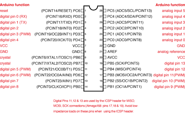
A Quick Word About Arduino Pins (ATmega168/328)

I recently received an email with a good question about pin usage on an ATmega328, and wanted to do a recap as well as offer a little worksheet that I use. I always use a standalone 328 vs dedicating a full Arduino in my project, it’s very economical, so pin assignments in the project are important.

Digital pins, or pins 0-13 on the Arduino are capable of input (detecting a high or low value) or output in a high or low state.

Analog input pins (A0 – A5) can also serve as input or output pins. These pins can also measure, in 1,024 steps, voltage applied to them. This is an invaluable function for measuring temperature, light, audio, or anything else that you need more than an off or on reading. These pins may also be referred to as pins 14-19.

Special pins to note: Pins 3, 5, 6, 9, 10, & 11 are capable of PWM output. Pins 0 and 1 are serial in and out. Pins 11, 12, & 13 are MISO, MOSI, and SCK respectively.

Often, when I do a project involving some LED’s, temp sensors, an LCD screen, buttons, and whatever else I can manage to hook up to it, I need to keep track of what pins I’m using for what function. I made a simple spreadsheet that has all the pins, there function, I/O checkbox, special functions, and DIP package assignments. This is a great tool to take a look at what I/O’s are being used for what, and I often use it to see if I can combine or move pins around to get the most out of my project. You can download it below in Numbers, Excel, or interactive PDF format. Excel does not support checkboxes, so the fields have been replaced with true and false. You can download the PDF if you wish, it has the text fields as well as the checkboxes. Below is also a link to the handy image on the top of this post. πŸ™‚

Numbers File (Mac)

Excel File (Windows)

PDF File

168/328 Pin Image (PNG)

Quietish Ray Gun

Hi everyone! I had an idea a while ago to modify this toy ray gun my kids have. The problem you ask? Noise. Too much noise. The bribe? more blinky in exchange for less noise. Here I will take a toy noise gun, upgrade the lighting, reduce the noise, and save parental brain cells! It’s a win win operation. So why the motivation to do this today? Because I gave it back to them this morning..

Arduino sketch here

Eagle file here

Schematic PDF here (if you don’t have Eagle)

Programming in a ZIF!

This is just a quick post about a board I made to program a whole bunch of ATmega 328’s for some kits I’m making. I am ordering the 328’s in bulk, so they are brand new and do not have an Arduino bootloader on them. One of the ways you can get an Arduino bootloader on a factory fresh 328 is use an Arduino Uno and a USBTiny. Sure, I could pop about 100 of these into an Uno, but that would be a lot of work as well as wear and tear on the 28 DIP socket on my Uno.

The answer? A ZIF socket! These are fantastic! Anyone who has installed/upgraded a CPU in a computer knows what these are. ZIF stands for Zero Insertion Force. That means you drop the chip in the socket very easy, then pull a lever down to secure the contacts and prevent the chip from bouncing out of there. Making swapping out a bunch of chips to program them a lot easier, faster, and less prone to damage to the pins or chips!

You can get these 28 Pin ZIF sockets at Adafruit, and for cheep! There is also a 40 pin version if your heart or project so desires. Sparkfun has this part in their Eagle library, if you don’t have it, and use eagle, I would get it. There is a lot of good stuff in there. πŸ™‚ And on another note, if you don’t have the Adafruit Eagle library, it’s worth having also.

You can download the board and schematic Eagle files here, or get the image version here.

And a big happy birthday to my first daughter Anna, who came into the world today!!! A future maker? Engineer? Who knows, but I can tell you this, She. Is. Awesome.

My new daughter!

πŸ˜€

Controlling high power (or high number of) LED’s with an Arduino

A while ago I posted about my bench lights, and have gotten a number of request for schematics and code. I’ll gladly put the code up, but I also wanted to explain what I did so that others can create their own, or at least change my design up as they wish. The transistors I’m using are TIP122’s. You can find the data sheet here. They will switch a lot of power, but keep in mind, they need to have adequate cooling if you are going to push them hard. Always remember, fire = bad.

I covered the basic schematic for a few LED’s in the video above, but if you have any questions, feel free to post them in the comments and I will answer as quickly as I can.

You can download the original (controller with LCD and hard buttons) code here.

You can also download the newer (serial controlled – adjustable level) code here.

Just a note, I will be using Vimeo from now on, but I will still put all my videos on YouTube as well.

Tic Tac Touch

OK, so I haven’t posted in a while because I have been working on some bigger projects, but yesterday, I took a two hour break and made a 2 player tic tac toe game. I did this with an Arduino and a 2.8″ touchshield from Adafruit.com. It’s pretty basic tic tac toe, and has score tracking, game logic (you can’t go twice in a row, and telling you if you win), and the ability to consume a chunk of time playing tic tac toe with my son. Below is the code, feel free to hack modify etc. If you play against a smart person (or yourself), you will have lots of Mosfet eye games! πŸ™‚

Download the code here. (Arduino 22 .pde file)