RGBW LED Controller v3.1

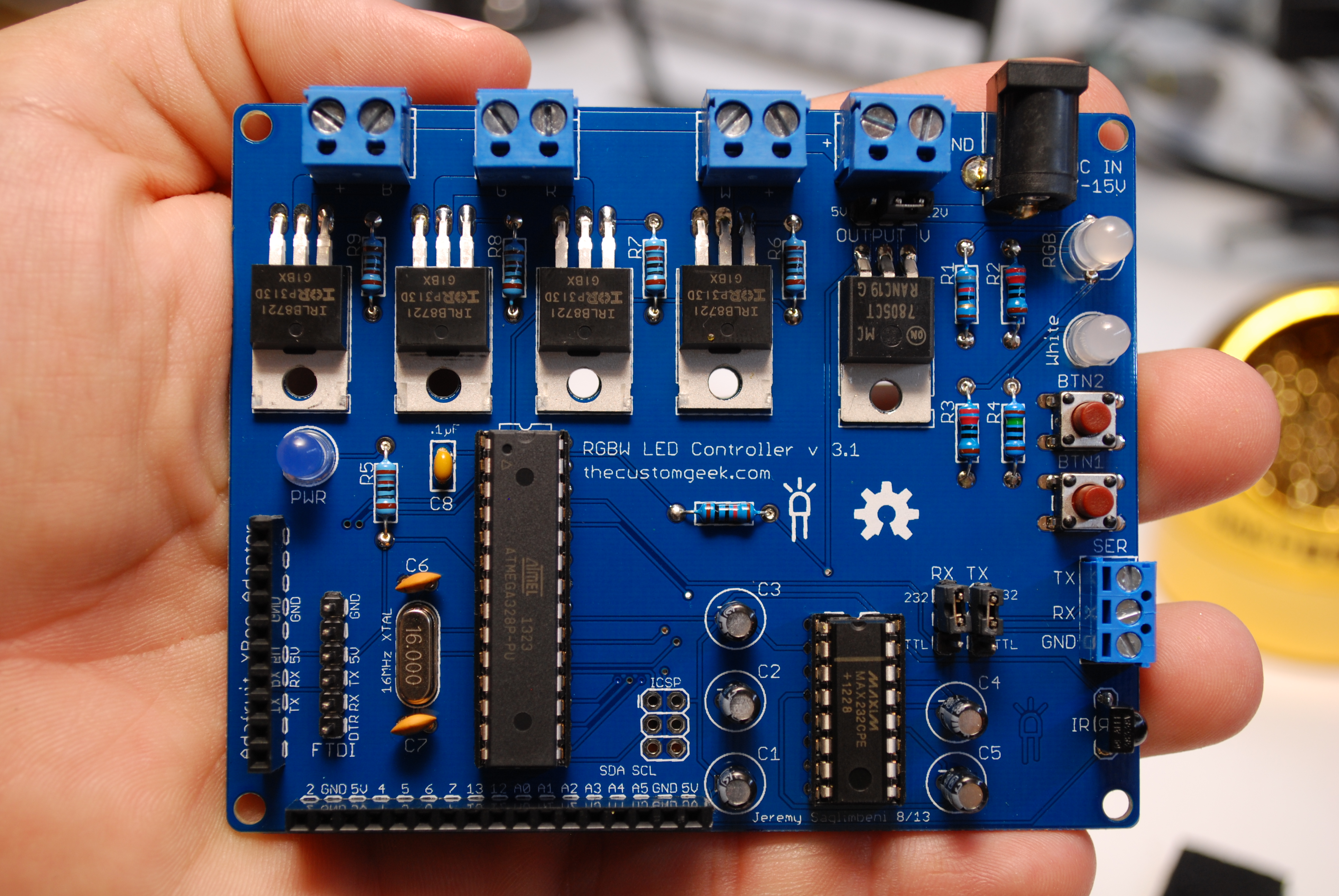
The new RGBW LED Controller is here! The video above shows some of the things it can do, but here is a list of improvements:

IRLB8721PBF MOSFET’s – More power!

Double sided and thicker board traces

More output headers

Cleaner board layout – All power and LED connections on one side – rounded corners

Improved serial capture method with feedback

Support for solid color commands (magenta, cyan, gold, RGB white, orange, light blue, light green, violet, pink, and RGB warm white)

More control from button inputs – long and short press commands

EEPROM memory of LED levels when powered off/on

IR control mode! – Full control of all channels and a memory recall function Get the remote here: http://www.adafruit.com/products/389

Wireless control via XBee! Get an Adafruit XBee adaptor here: http://www.adafruit.com/products/126

Backward compatible! The new software set will work on version 3.0, 2.2, and 1.9!

In stock and shipping from our store now!

New firmware and cad files available at https://github.com/jersagfast/RGBW-31.

The manual is here: RGBW LED Controller v31

RGBW31

Really Small(s) GPS

Hi peeps, I have been wanting to make a small GPS device (GPS receiver and some sort of screen) that I could carry around for a while now, but I didn’t want it to be too big, so I made this. Mission accomplished.

This unit is explained in the video above, but is basically a GPS receiver, 1 CR1220 battery for the RTC on the GPS breakout, one of my Square Inch of Goodness boards, one 128×32 OLED display, three 6mm buttons, and a 400mAh Li-Po Battery (from Sparkfun). It even has FTDI headers on it so I can update the firmware with ease (with my own FTDI adapter!). The awesome part is that all of those things fit in an Altoids Smalls tin, measuring 2.15″ (W), 1.35″ (L), and .56″ (H), or 55mm (W), 34mm (L), and 14mm (H).

The GPS breakout board is from Adafruit and uses the MTK3339 GPS module, and man does it work well. I have had other GPS modules that worked, but it was a fight. If you’re thinking about putting GPS in a project, use this. They also have a great library for it. They even have the raw MTK3339 GPS module if you want to use your board. Read the Adafruit product page for all the features, there are many.

The 128×32 OLED display is also from Adafruit, it works well and has the typical OLED crispiness. Very easy to read, even in sunlight, for the size and you can even multiply the text size if you want to.

So I’m going up to NY in a few days, and I wanted a new and exciting way to talk with the TSA folks, so I figured this would work. (kidding) If only Hollywood had not trained everyone to think a gadget with a few wires and a flashing red LED, that they didn’t understand, was a bomb.. ugh. (not kidding)

*UPDATE – there is a set on Flickr for this with teardown pictures.

*UPDATE #2 – Oops, I forgot to put the link to the code on Github. 0_0

Yamaha AG Stomp Mod

I wanted to do a quick post on a mod I did to a Yamaha AG Stomp. An AG Stomp is a acoustic guitar effects pedal that was made in 1994, but no longer available.

The need was this: to gain more real estate space under a keyboard that was full of pedals, controllers, and switches. So the need to switch banks without taking up the whole size of the pedal was the goal. The answer was to build a small (3.64″L x 1.52″W x 1.22″D) pedal that had a single switch, had an easy way to tell witch bank you were on, have a signal indicator, and be road tough. The end result made the customer very happy, and he requested that I share, so here it is. 🙂

You can check out Austin Biel at austinbiel.com, an awesome musician (including the best keyboard player I have heard), and an outstanding friend.

i Get a charge out of this!

I had a post a while back on charging an iDevice (iPhone, iPad, iPod) and talked about and showed a schematic for the charging circuit. This design is based (and the schematic is almost exact!) off of Ladyada’s Reverse engineering Apple’s secret charging methods. (video link, it’s good, you should watch it!) I give her full credit for the circuit. Now, the boards I whipped up in a few hours, and had it made from DorkbotPDX service. I sent off the files and 2 weeks later, I got three perfect purple PCB’s. The boards cost a total of $4.69. Shipped. You can’t beat that with a stick! Now, I have a nice little iDevice charger that accepts standard 5 volt power from any standard power supply. Although I do tend to favor 5V 2A supplies from Adafruit.

I used the same circuit I had in the old post, just added an LED and resistor for a power indicator. I had an old cell phone from 2006, and saved the keypad because it lit up blue. (Can you blame me?) Now, 6 years later those tiny 603 blue LED’s come in handy. I got the 603 resistor from an old PC motherboard. Motherboards have a slew of SMD things on them. So I fired up the hot air rework station, grabbed my tweezers, and voila! SMD parts! (I did order some reels of 603 resistors and LED for use in future kits, sorry peeps, no old motherboard parts for you!) I use a good pair of tweezers, and a viewfinder from an old camcorder to inspect my work. “But Jeremy? Where do you keep all of those SMD parts?” you ask? Good question, I use these awesome Modular Snap SMD component storage boxes from Adafruit. They have spring loaded tops, and they are modular, you can form them in any configuration you want! How cool is that?!

Continue reading

Stress Relief..

So I had a long day, and as I was cleaning my office I found some LED’s that were less than optimal. I’m not usually destructive, but it was time to blow them up. I love how the LED’s physically move as they die, so cool. The picture below is the last LED that smoked (click for full size), it was a trooper, lots of smoke. Outtakes at the end of the video.