RGBW LED Controller v3.1

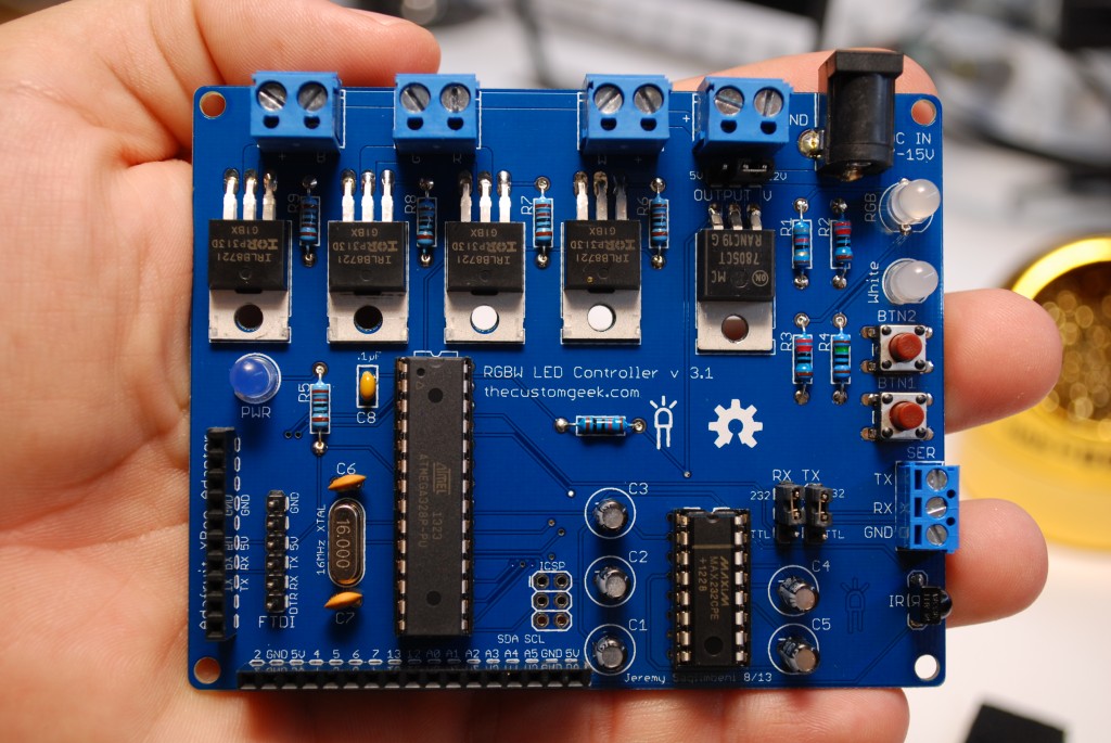
The new RGBW LED Controller is here! The video above shows some of the things it can do, but here is a list of improvements:

IRLB8721PBF MOSFET’s – More power!

Double sided and thicker board traces

More output headers

Cleaner board layout – All power and LED connections on one side – rounded corners

Improved serial capture method with feedback

Support for solid color commands (magenta, cyan, gold, RGB white, orange, light blue, light green, violet, pink, and RGB warm white)

More control from button inputs – long and short press commands

EEPROM memory of LED levels when powered off/on

IR control mode! – Full control of all channels and a memory recall function Get the remote here: http://www.adafruit.com/products/389

Wireless control via XBee! Get an Adafruit XBee adaptor here: http://www.adafruit.com/products/126

Backward compatible! The new software set will work on version 3.0, 2.2, and 1.9!

In stock and shipping from our store now!

New firmware and cad files available at https://github.com/jersagfast/RGBW-31.

The manual is here: RGBW LED Controller v31

RGBW31

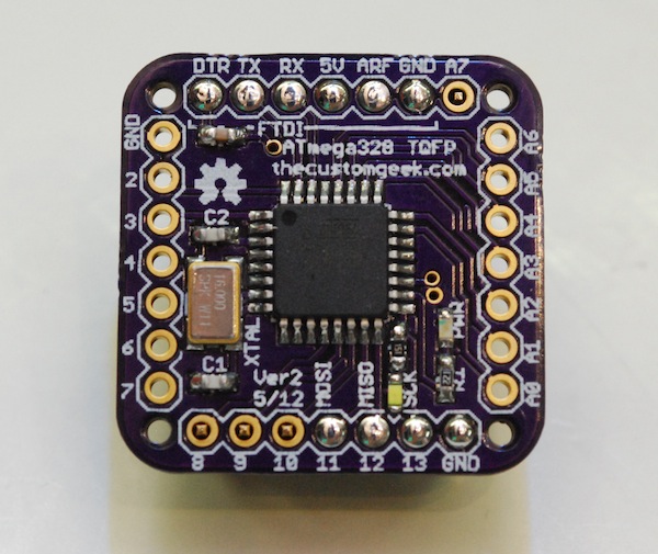
One Square Inch of Goodness

So a while ago I discovered that I needed a microcontroller in a really tight space. I tried an ATmega328P PU (DIP package), but try as I may, It would not fit. The answer? The ATmega328P AU (TQFP) this is a much smaller package, and for an added bonus, it has 2 extra ADC’s. This a great little board to squeeze in various projects, and opens the door to some very cool stuff I have coming up. Some of you might remember I put this board in a project I did a while ago when space was very limited. It’s just a handy little board to have on hand. 🙂

In the video above, I show some soldering with TQFP packages, as well as a little soldering with hot air. I need to figure out a way to record video from my brain. It would make things so much easier..

Oh, I almost forgot, the flux pen I used, found at Sparkfun.

The Eagle files for this board are on my Github page. Or just the schematic PDF.

i Get a charge out of this!

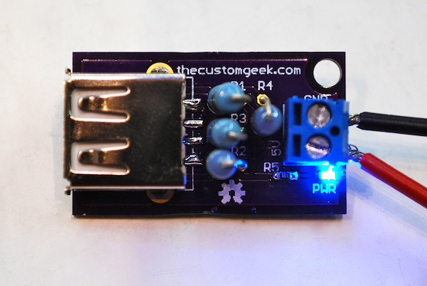
I had a post a while back on charging an iDevice (iPhone, iPad, iPod) and talked about and showed a schematic for the charging circuit. This design is based (and the schematic is almost exact!) off of Ladyada’s Reverse engineering Apple’s secret charging methods. (video link, it’s good, you should watch it!) I give her full credit for the circuit. Now, the boards I whipped up in a few hours, and had it made from DorkbotPDX service. I sent off the files and 2 weeks later, I got three perfect purple PCB’s. The boards cost a total of $4.69. Shipped. You can’t beat that with a stick! Now, I have a nice little iDevice charger that accepts standard 5 volt power from any standard power supply. Although I do tend to favor 5V 2A supplies from Adafruit.

I used the same circuit I had in the old post, just added an LED and resistor for a power indicator. I had an old cell phone from 2006, and saved the keypad because it lit up blue. (Can you blame me?) Now, 6 years later those tiny 603 blue LED’s come in handy. I got the 603 resistor from an old PC motherboard. Motherboards have a slew of SMD things on them. So I fired up the hot air rework station, grabbed my tweezers, and voila! SMD parts! (I did order some reels of 603 resistors and LED for use in future kits, sorry peeps, no old motherboard parts for you!) I use a good pair of tweezers, and a viewfinder from an old camcorder to inspect my work. “But Jeremy? Where do you keep all of those SMD parts?” you ask? Good question, I use these awesome Modular Snap SMD component storage boxes from Adafruit. They have spring loaded tops, and they are modular, you can form them in any configuration you want! How cool is that?!

Continue reading

RGBW LED Controller

Control your blinky!

Hi everyone, I am happy to announce that I have completed my RGBW LED controller kit and it is now for sale! This kit is a LED controller that features an embedded ATmega328 with an Arduino bootloader for easy programming, 4 channel LED control with dimming, 5 or 12 volt output, IR receiver, XBee header, RS-232 or TTL serial I/O, 2 push buttons, 12 pin extensions for all unused pins (6 analog and 6 digital), and power and channel LED indicators. You can control 5 or 12 volt LED’s via serial with adjustments to the level of any channel with ramping to the desired level, rate of ramping, color cycle start and stop, rate of color cycle, length of stay on each color during cycle. Fans and motors can also be driven with ease. You can buy one for only $35 with the Paypal link below! Be sure and also visit the complete assembly tutorial! Power supplies, RGB and white LED stripsFTDI Friend or FTDI Cable and XBee’s and XBee adapters are available at Adafruit!

Version 2.2 is shipping! Please go to the assembly page for details.

Automation Intro

I wanted to give a tour/crash course on automation systems, so I put together a video showing some of what an automation system can do. I ran through everything kind of fast, so I will do more videos getting into more details on specific functions of sub systems, like lighting, audio, security, etc. This video also shows my RGBW Controller working in my house. 🙂

The system I have is an HAI Omni Pro II. I have been installing automation systems since 2005, and they have proven to be an awesome choice.

For a future project, I would like to replace the Omni with a BeagleBone. 🙂