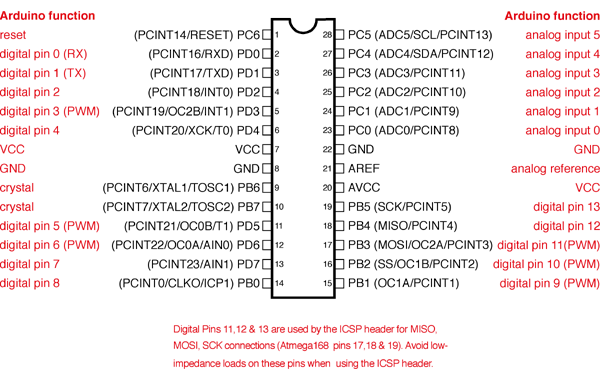
I recently received an email with a good question about pin usage on an ATmega328, and wanted to do a recap as well as offer a little worksheet that I use. I always use a standalone 328 vs dedicating a full Arduino in my project, it’s very economical, so pin assignments in the project are important.
Digital pins, or pins 0-13 on the Arduino are capable of input (detecting a high or low value) or output in a high or low state.
Analog input pins (A0 – A5) can also serve as input or output pins. These pins can also measure, in 1,024 steps, voltage applied to them. This is an invaluable function for measuring temperature, light, audio, or anything else that you need more than an off or on reading. These pins may also be referred to as pins 14-19.
Special pins to note: Pins 3, 5, 6, 9, 10, & 11 are capable of PWM output. Pins 0 and 1 are serial in and out. Pins 11, 12, & 13 are MISO, MOSI, and SCK respectively.
Often, when I do a project involving some LED’s, temp sensors, an LCD screen, buttons, and whatever else I can manage to hook up to it, I need to keep track of what pins I’m using for what function. I made a simple spreadsheet that has all the pins, there function, I/O checkbox, special functions, and DIP package assignments. This is a great tool to take a look at what I/O’s are being used for what, and I often use it to see if I can combine or move pins around to get the most out of my project. You can download it below in Numbers, Excel, or interactive PDF format. Excel does not support checkboxes, so the fields have been replaced with true and false. You can download the PDF if you wish, it has the text fields as well as the checkboxes. Below is also a link to the handy image on the top of this post. 🙂
